1. Overall Architecture
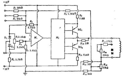
The circuit adopts a differential operational amplifier M1 as the front stage. The command signal and system feedback signal are input via terminal 1, while terminal 2 serves as the balance input for zero adjustment. The difference signal is amplified and phase-inverted, then transmitted to the driver stage M2. The final stage adopts a push-pull output configuration.
In the circuit, M1 functions as a differential operational amplifier. Terminal 1 is the signal input port, and terminal 2 is connected to the bias balance network composed of R4 and R7, forming a typical differential input structure.
The output signal is inverted and sent to the driver stage M2. The final stage is a push-pull power amplifier composed of BG1 and BG2.
2. Current Flow Direction
When the input signal of M1 is negative, the output of M1 turns positive and the output of M2 turns negative. BG1 is forward biased and turned on. The current flows from the +15V power supply through R9, BG1, R10, the servo valve coil, then to the parallel network of R16, R13 and R12, and finally to ground.
Reverse current path:
Ground → R12/R13/R16 parallel network → servo valve coil → R10 → BG2 → R11 → −15V power supply.
Ground → R12/R13/R16 parallel network → servo valve coil → R10 → BG2 → R11 → −15V power supply.
3. Component Functions
Resistors play a current-limiting role. The bias voltage applied to input terminal 2 of M1 is used to control the balance of the amplifier. Adjusting R13 changes the feedback quantity, so as to regulate the gain of the amplifier.
R9 (together with R8) and R11 are connected in series to the emitters of BG1 and BG2 respectively, limiting the maximum output current and protecting the power transistors and the servo valve coil.
The bias network (R4/R7) at input terminal 2 is used for amplifier zero balance. R13 is an adjustable feedback resistor; changing its resistance can adjust the closed-loop gain. 
4. Dither Signal
To reduce the dead zone of the servo valve and improve its sensitivity, a dither signal is introduced through terminal R14, and the dither current is adjusted by R15.
In the circuit, the dither signal is injected into the servo valve coil loop via R14 and adjustable resistor R15. The injection current of the dither signal can be regulated by R15.