Abract:This paper describes nozzle‑flapper servo‑valve operation. It covers its two‑stage pilot‑power structure, key components, force‑feedback closed‑loop process, aerospace strengths, and clears up typical misconceptions of this high‑precision hydraulic component.
Why does a nozzle‑flapper servo valve use a two‑stage structure?
Many beginners ask a question. We can control flow with a single four‑way spool valve. Why does the nozzle‑flapper servo valve use a complex two‑stage structure (nozzle‑flapper pilot stage plus four‑way spool power stage)?
The reason comes from a core conflict of servo systems. High‑precision fast control and large‑flow high‑power output cannot be achieved easily at the same time.
Limitations of a single‑stage four‑way spool valve
Take the typical three‑land four‑way spool valve as an example. To move the spool for large flow, the system needs huge electromagnetic thrust. Larger spools for higher flow need more thrust.
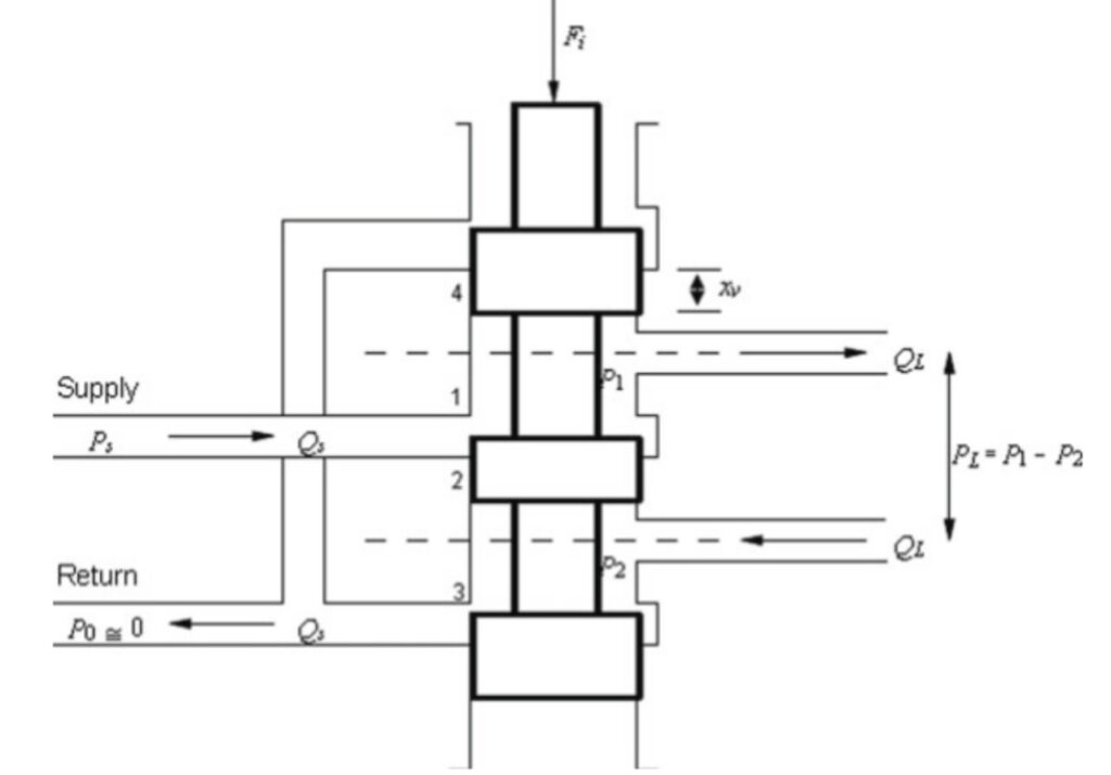
However, high‑thrust electromagnets have clear disadvantages. They are big and heavy. More importantly, they have slow response and poor control accuracy. Their spool displacement accuracy is only about tenths of a millimeter. This cannot meet the micrometer‑level requirements of aerospace flight control.
Two‑stage design realizes hydraulic power amplification
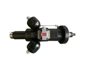
The two‑stage servo valve solves this conflict through step‑by‑step power amplification. Our dual nozzle‑flapper servo valves can directly replace MOOG G761, G631 and 072 series.
- Pilot stage (nozzle‑flapper): for precise control. It receives weak electric signals and produces micrometer‑level mechanical movement. Then it turns this tiny movement into hydraulic pressure difference. Hydraulic force replaces electromagnetic force to provide driving power.
- Power stage (four‑way spool): for power output. Driven by the pressure difference from the pilot stage, the spool moves. It outputs large‑flow high‑pressure hydraulic oil to drive cylinders or rudders.
We can use a car gearbox as a simple comparison. The pilot stage works like a steering wheel. It needs little force for precise control. The power stage works like an engine and gearbox. It provides strong power. In short, small‑force precise control produces high‑power stable output.
That is why aerospace flight control widely uses two‑stage nozzle‑flapper servo valves. They offer micrometer‑level precision and millisecond‑level response. Meanwhile, they can output large hydraulic power for aircraft rudders.
Four core parts of a nozzle‑flapper servo valve
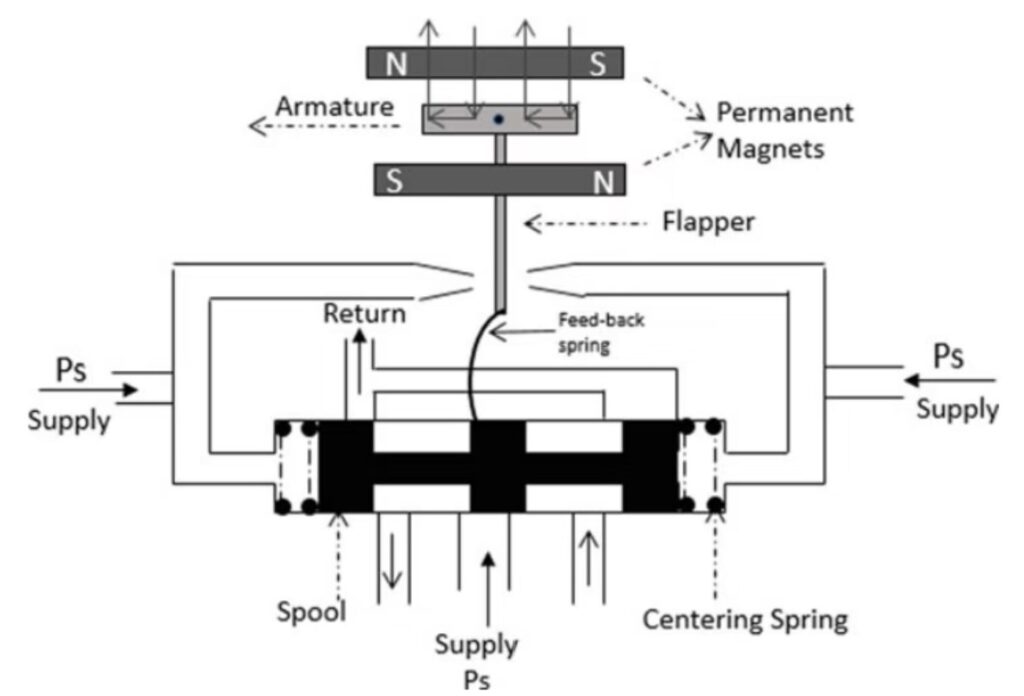
A complete spring‑feedback nozzle‑flapper servo valve includes four key parts.
| Component | Installation position | Main function |
| Torque motor | Top of servo valve, electric signal port | Converts electric current signal into mechanical torque |
| Nozzle‑flapper pilot stage | Below torque motor, above spool valve | Converts tiny flapper movement into control pressure difference for the spool |
| Four‑way spool power stage | Main body of servo valve, below pilot stage | Amplifies flow and power. Driven by pressure difference, it outputs adjustable large hydraulic flow |
Four‑step closed‑loop process: from current input to flow output
Step 1: Current input. Torque motor turns electric signals into mechanical rotation
The torque motor has permanent magnets, coils with armature, and a torsion spring. The bottom of the armature connects to the flapper of the pilot stage. The armature can rotate a small angle around the center of the torsion spring.
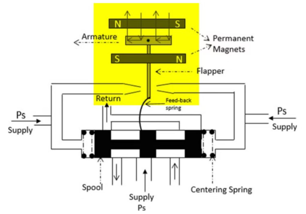
Here is how it works:
- The controller sends control current (normally ±10 mA) to the coils.
- Magnetic poles form on both ends of the armature. They interact with magnetic fields from permanent magnets. As a result, rotation torque acts on the armature.
- The torque overcomes spring force. The armature rotates. Rotation angle is directly proportional to input current. If current reverses, rotation direction also reverses.
Important note: The flapper only moves at the micrometer scale. Its maximum travel is 30‑100 μm, less than the diameter of a human hair. This tiny travel creates the high precision of the servo valve. Ordinary proportional valves and solenoid valves cannot reach this performance.
Step 2: Flapper deflection. Pilot stage turns mechanical movement into pressure difference
The pilot stage has two symmetric fixed nozzles and one movable flapper in the middle. High‑pressure oil passes two fixed orifices and enters front chambers of the two nozzles.
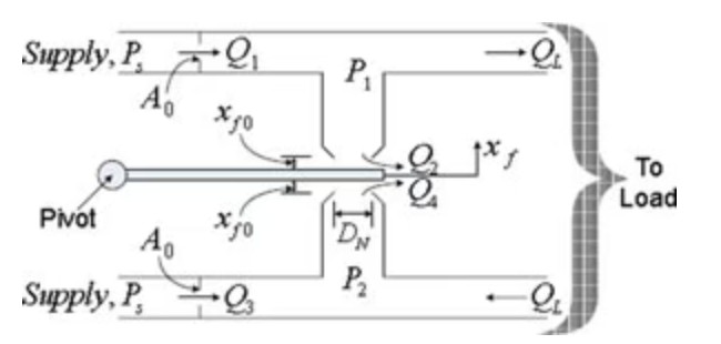
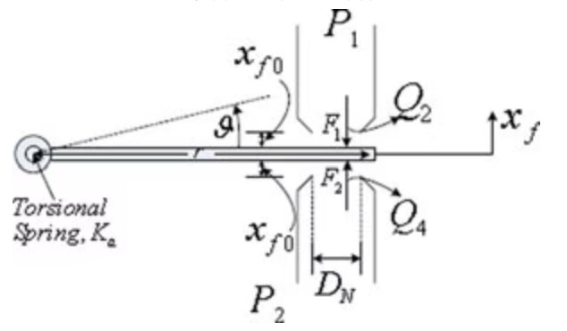
The gap between nozzle and flapper acts as return‑flow passage to tank. If the gap becomes larger, more oil flows back and chamber pressure drops. If the gap becomes smaller, less oil flows back and chamber pressure rises.
- Middle position (zero input current): The flapper stays centered. Two nozzle gaps are equal. Pressure P1 equals P2 on two sides of the spool. The spool keeps static and no flow outputs.
- Flapper deflects (with input current): One gap shrinks and its chamber pressure rises. The other gap opens and its chamber pressure falls. Then a pressure difference builds up across the spool. This hydraulic force pushes the spool to move.
This shows the advantage of hydraulic amplification. Only several micrometers of flapper movement can generate pressure difference of several to tens of bar. It produces hundreds of newtons of driving force. Only small electric current is needed to move the flapper.
Step 3: Pressure difference drives power‑stage spool. Spool displacement produces large‑flow output
The power‑stage is a four‑way spool valve. Both ends of the spool connect to the two nozzle chambers of the pilot stage. Spool position fully depends on the cross‑spool pressure difference.
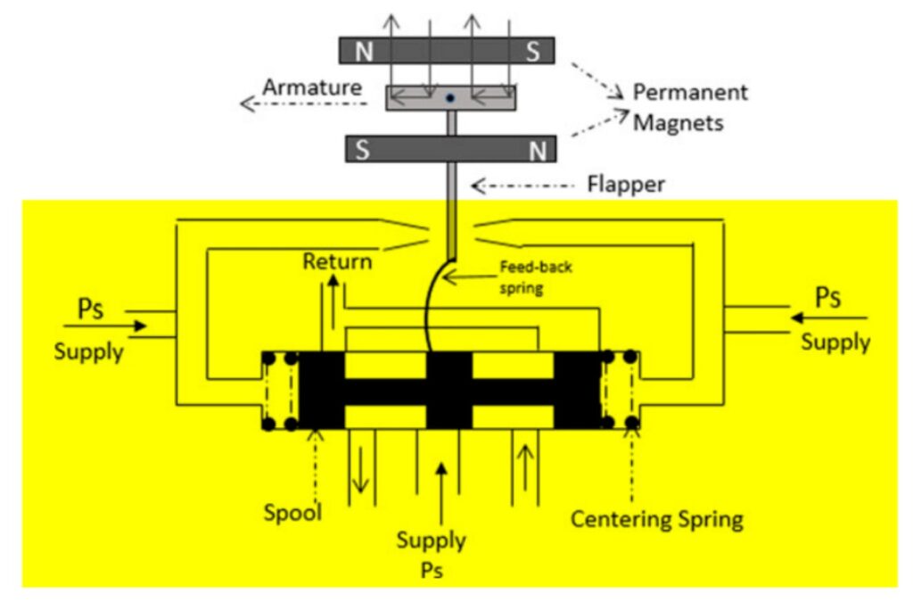
- Pressure difference from pilot stage pushes the spool to move linearly.
- Spool movement opens valve ports. Pressurized oil flows into actuator port A, and return oil flows back to tank via port B. Larger spool displacement creates bigger port opening and higher output flow. So the actuator runs faster.
- If input current reverses, flapper moves in the opposite direction. Pressure difference reverses too. The spool moves backward and the actuator changes direction.
Under rated conditions, spool displacement and output flow keep linear relation. Input current decides spool opening. Thus electric signals can accurately control hydraulic flow. This matches the flow‑gain characteristic Kq.
Step 4: Force balance with feedback spring to complete closed‑loop control
Many readers think the process ends at Step 3. In fact, the feedback‑spring closed‑loop is the key for accurate and stable performance of the servo valve.
One end of the thin feedback spring fixes at the center of the flapper. Its ball‑shaped lower end fits into the groove of the spool. When the spool moves, it bends the feedback spring and produces reverse feedback torque on the flapper.
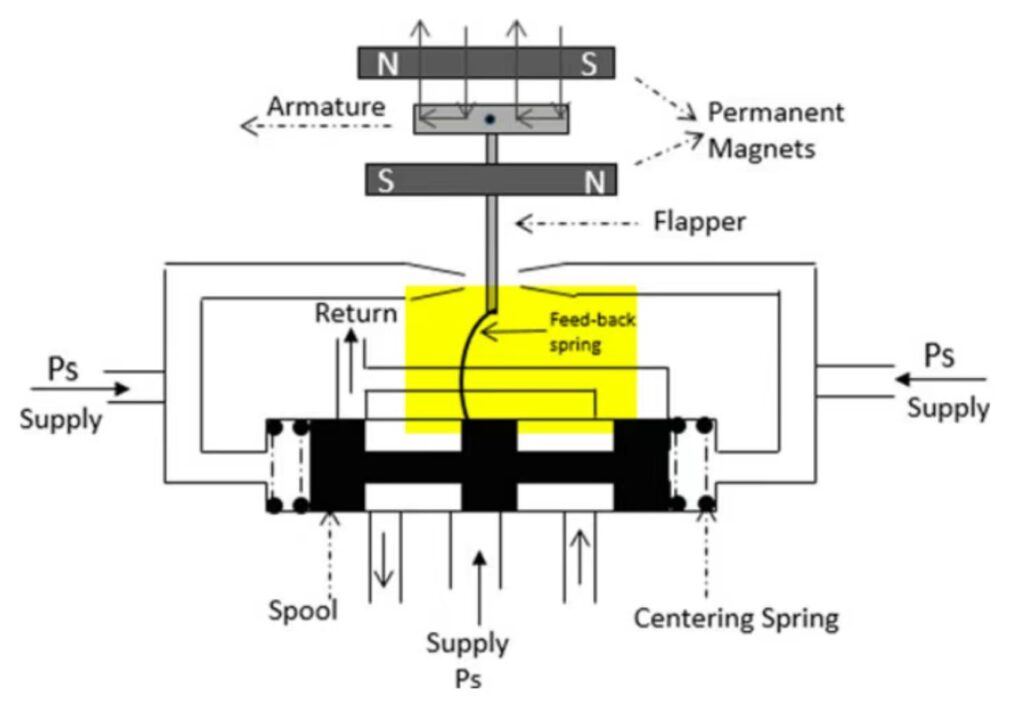
Closed‑loop balance process:
- Input current creates forward electromagnetic torque. The flapper deflects and builds pressure difference to push the spool.
- Spool movement bends the feedback spring. Then reverse feedback torque increases with spool travel.
- When feedback torque equals electromagnetic torque, the flapper returns near its center position. Cross‑spool pressure difference disappears and the spool stops moving at a stable opening.
Finally, a linear rule forms. Input current value matches stable spool displacement. With fixed current, the spool holds its opening and outputs steady flow. If current changes, spool opening and output flow change accordingly.
This is not simple open‑loop control. The internal force‑feedback closed‑loop reduces disturbance from flow force and load change. So the servo valve keeps stable flow control.
Four reasons for wide use in aerospace flight control
- Ultra‑high control precision at micrometer level. Pilot‑stage micro‑movement makes spool displacement accuracy within 1 μm. Flow control accuracy reaches 0.1 % of rated flow. It meets the requirement of aircraft rudder deflection within ±0.1°.
- Fast dynamic response and high bandwidth. Spool driving force comes from hydraulic pressure instead of electromagnets. Response reaches millisecond level. Bandwidth can reach tens to hundreds of hertz.
- High power amplification and strong anti‑disturbance ability. Milliamps‑level weak current controls large flow output. Power‑amplification ratio can reach over 10 million. Internal force‑feedback loop resists load and flow‑force disturbance. It works stably under complex high‑altitude conditions.
- Excellent null performance. It has low null leakage and good linear gain near null position. High‑precision fine adjustment works well at middle spool position. This fits frequent small rudder adjustments during aircraft cruise.
Three common misunderstandings for beginners
Misunderstanding 1: The flapper needs large travel to drive the spool
This is wrong. Maximum flapper travel is only 30‑100 μm. Only several micrometers of movement can build enough pressure difference for full‑range spool travel. This tiny travel brings fast response and high precision for the servo valve.
Misunderstanding 2: The feedback spring returns the spool to middle position
This is wrong. Centering springs on both ends of the spool realize spool centering. The feedback spring mainly builds the force‑feedback closed‑loop. It converts spool displacement into reverse torque. It creates linear relation between input current and spool travel. This is the core of high‑precision servo‑valve control.
Misunderstanding 3: Nozzle‑flapper servo valves are sensitive to contamination and only work in laboratories
This is wrong. Small nozzle‑flapper gaps demand clean hydraulic oil, but the servo valve is not limited to laboratories. In aerospace systems, oil pollution keeps within NAS 8 class. Then nozzle‑flapper servo valves can run reliably for tens of thousands of hours. For industrial use, three‑stage filtration also brings long service life better than common proportional valves.